
High Performance PCB Material Considerations
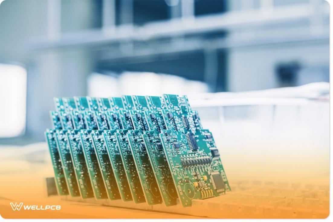
Every PCB stack-up you design for your circuit board will involve a variety of materials. The materials you choose play a crucial role in determining factors like power/signal loss, interconnect impedance, copper surface roughness, and temperature rise in your PCB.
Since not all base materials are suitable for every application, it’s essential to choose the right one to optimize performance. Below is a comparison of PCB material properties to help you select the most appropriate base material for your circuit boards.
What Are Pcb Material Considerations For High Performance?
When choosing a base material for a PCB, you’ll need to consider the different material properties.
Relative Dielectric Constant
The relative dielectric constant is a complex figure made of dissipation factor (Df) and relative permittivity (Dk).
Dissipation is the measure of how a PCB material experiences power loss, which is important for distortion minimization and signal integrity. When working with high-performance PCBs, it’s vital to use materials with a low dissipation factor. Normally such materials have a dissipation factor of lower than 0.005.
Permittivity refers to the ability of a material to store energy in an electric field and measures the electrical insulation of a material. It is important for ensuring signal integrity and impedance matching. Just as with the dissipation factor, high-performance PCBs require materials with a low dielectric constant (lower than 4) as they serve as ideal insulators for copper traces and power planes.
However, these values are mainly dependent on the signal frequency and increase as the frequency decreases. It’s best to opt for a material with a fairly constant dielectric constant despite signal frequency variations and circuit lifetime.
|
Df |
Dk |
|
|
High |
Over 0.02 Less common in PCB designs, resulting in high signal loss. Only used when electrical performance isn’t the main concern. |
Over 10 Tighter signal coupling, commonly used in high-performance designs, such as power amplifier circuits and matching impedance |
|
Medium |
Between 0.005 -0.002 Maintain a balance between cost and electrical performance, ideal for a number of general-purpose applications |
Between 4 -10 Maintain a balance between cost and high-frequency performance, used in applications such as microstrip transmission lines and digital communication systems |
|
Low |
Under 0.005 Used in high-frequency applications and high-performance designs whereby minimizing signal loss is a priority |
Under 4(materials such as PTFE) Maintain signal integrity and minimize signal loss at high frequencies, ideal for high-frequency applications like RF circuits and microwaves. |
Conductor Loss
Conductor losses come in DC and AC varieties. The electrical conductivity establishes the skin depth, which in turn determines the AC losses. Keep in mind that conductor losses in copper on your PCB substrate relate to the roughness of the copper surface, which increases loss in your system and changes the impedance of your interconnect.
Thermal Conductivity
Thermal conductivity dictates the rate at which heat dissipates away from the substrate during operation and concludes the temperature rise with respect to the ambient temperature. Therefore, it determines your strategy for thermal management, such as using a fan or heat sink to keep components cool.
Coefficient of Thermal Expansion (CTE)
The coefficient of thermal expansion indicates how the board expands as the temperature increases. CTE is anisotropic therefore, the board will expand in different directions at different rates. However, engineers only care about expansion on the z-axis.
Glass Transition Temperature (Tg)
The glass transition temperature indicates a sudden increase in the coefficient of thermal expansion as temperatures increase. The CTE value below Tg is smaller than the CTE value above Tg.
Dispersion
The relative dielectric constant varies with the signal’s frequency, so dispersion is not a single value. Instead, it is a characteristic that describes how signals at different frequencies experience varying propagation delays in an interconnect.
Mechanical and Chemical Properties
When assessing the chemical resistivity the environment you plan on exposing your circuit board to plays a deciding factor. You should choose a material with high chemical resistance and low moisture absorption. Also, the material should feature flame retardant properties whereby it won’t burn for over 50 seconds in case of flame combustion.
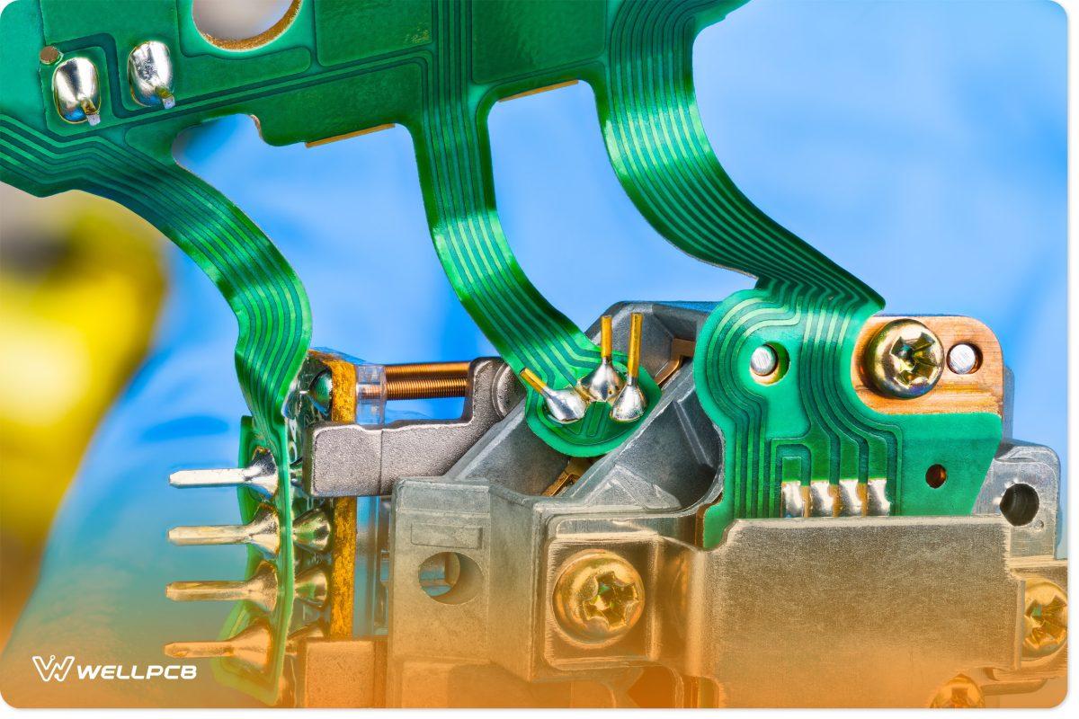
Flexible and rigid-flex PCBs need specific mechanical properties for them to fold and bend around parts without affecting the integrity of the material. If you bend your laminate layers, your copper layers begin to peel off.
Also, your material should feature sufficient flexural strength so that it not only bends but maintains the physical stress and angle for the circuit board’s life. Lastly, the PCB layers could start unraveling at specific temperatures; therefore, you should determine the delamination time.
Conclusion
Following the above guidelines will help you choose a reliable material and create a robust, high-performance PCB. For all your PCB needs and inquiries, feel free to contact WellPCB. We are experienced in designing and manufacturing high-performance circuit boards, whether they are rigid-flex boards, flexible boards, or standard rigid boards. Any questions about the type of material that will better serve your needs? We are ready to inform you about any potential problems that a material could pose to other materials.


